Master's Thesis
May 28, 2014 00:00 · 3319 words · 16 minutes read
Intro
I’ve decided to begin blogging my various endeavors in software development and electrical engineering hackery. To kick it off, I’m writing a post describing the work I did for my Masters of Science in Electrical Engineering thesis. This post will start it off with a brief introduction/overview, then I’ll cover individual aspects of the project.
You can read my full thesis via my advisor’s website, and all source code is available to view at github.com/serdmanczyk/masters-thesis/.
The title of my thesis was “Adaptive Deployment of Mobile Sensor Nodes.” Unfortunately, like many academic paper titles, that comes off a bit vague. More specifically, my thesis involved researching a method for the dynamic deployment and maintenance of of mobile robots to act as a ‘wireless tether’ of repeaters for radio communications between a deployed robot and its base station in restrictive environments.
That’s quite a mouthful, but in reality it’s actually pretty simple. Let’s consider an example use scenario:
Consider you’re deploying mobile robots into a tunnel, collapsed building, or some other environment where radio communications may become restricted due to interference from obstacles. There’s various reasons you may want to do this: data gathering, equipment maintenance, locating disaster survivors, etc.. You need a way to repeat your signal to the deployed robot, and simply beefing up your transmitter strength won’t work. You could try manually placing radio repeaters, but that’s not feasible in dynamic scenarios. Instead, you could deploy robots that can intelligently move themselves in positions akin to better signal strength as well as recover their ‘tether’ in the case a node is damaged or destroyed. Applications like this were the aim of my thesis.
Designing a system for these situations sounds super cool, and what I completed with my thesis would make a good bottom layer for one of these example applications. Unfortunately I was just one person, was completing my thesis alongside working full-time, had limited access to materials from my universities lab due to time/distance constraints, as well as had a limited personal budget, so obviously my thesis did not involve me designing and implement a full system of actual moving robots that can rescue you from a collapsed building.
What I did do, was designed a piece of such a system and physically simulate it using my laptop and a few embedded boards. Other pieces required for a full system would include the parts for path navigation, collision avoidance, robot localization, pattern recognition, etc.
My resulting application broke down into three hardware pieces performing three general tasks. The hardware pieces were:
- A base station run via Python. In my case a laptop, but adaptable to anything that runs python (e.g. Raspberry Pi)
- A tether of mobile nodes programmed in C++, implemented with Renesas Sakura boards (provided by my advisor), but easily adaptable to an Arduino device
- XBee 802.15.4 radios for handling wireless communications
The three general tasks were:
- The base station would dynamically deploy nodes as needed when the most recently deployed node exceeded range
- Deployed nodes would maintain distance between each other in order to maintain maximal signal strength
- In the case a node was lost, the system of nodes would maneuver and re-connect in order to heal the wireless communications tether
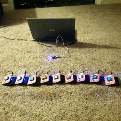
I unfortunately did not get access to sufficient equipment to make the mobile nodes autonomously mobile, and instead had to simulate movement by having the Sakura boards light LEDs indicating their desired direction and then move the boards by hand. However, in my code I did provision for the output of a pulse-width-modulated signal to control a servo or DC motors.
That concludes the basic, top-level overview, now let’s delve into how I handled the networking layer in my application.
Networking
The XBee 802.15.4 nodes are called as such because they implement the low-level 802.15.4 protocol. This is a protocol designed for low-powered device networking, primarily embedded applications, that gives slower speeds but with lower power requirements. The 802.15.4 protocol provides accommodations for layers one and two of the OSI model. On layer one they handle converting the digital output to radio waves as well as direct sequence spread spectrum (DSSS) modulation to avoid radio interference. On layer two it provides Media Access Control techniques such as carrier sense multiple access with collision avoidance (CSMA/CA) to prevent radios attempting to access the communications medium at the same time. What 802.15.4 does not provide is networking, so it was up to my application to handle OSI layer three and up.
There’s various ways to configure the XBee nodes to communicate, I won’t expound on them here. In short, I chose to use the XBee API mode to handle communicating with the radios because of the flexibility, speed, and control it offered. I chose not to use Full Function Device / Reduced Function Device functionality, or even ZigBee, to handle networking for a slew of reasons I won’t waste space divulging into here. I’ll just say they were either too power hungry, had limitations too great, or just didn’t fit.
With XBee API mode, all messages sent and received from the radio needed to be packed in a frame format. In particular the transmission request frame would contain the following information:
- The destination node address
- A frame ID (used to track transmission success)
- Whether or not the radio should return a ‘success’ packet if transmission succeeds
- The message itself
The received packet would contain the following:
- Source address
- Received signal strength indicator (RSSI) measured on message detection
- An optional byte to denote if message is a broadcast message
This provided all the ingredients I needed to handle networking in-app and on-the-fly. The RSSI from the received packets is particularly interesting, as it allows the application to keep record of signal strength with nearby neighbors without additional overhead. Another good reason to use API mode, that I’ll delve into in the next part.
In networking, it’s common for devices in charge of routing to manage a table containing information and routes to known addresses. In the case of my application, networking is pretty simple: either a packet is going towards the base station or away from the base station. This kept routing tables down to two addresses: the neighbor to the front and the neighbor to the back. Of course, the base station would keep check on all nodes deployed, but would only communicate to the nearest node. For deployed nodes, the front and back neighbor are assigned by the base station on deployment.
So, I have a way to address which nodes to talk to, and I have a way to route messages to all other nodes in the system. Done, right? Well, of course I had more problems.
As is the nature of networking, errors will occur. Packets will be lost, so I needed a way to track specifically which packets and attempt to retry. Luckily the optional bits in the transmission frame allowed my app to track which messages had succeeded or not. If a message failed, that radio would pass a message back with a frame ID, and I would use the frame ID to retrieve the message from a short-term cache and retry. If it failed too many times, I abandoned and deleted it. This provided layer two feedback and error handling.
Still, there was some trouble with multi-hop messages being lost, so the next step was to have nodes send an explicit acknowledge message for messages meant to traverse several nodes. If no acknowledge from the destination node within a specified time frame, I would retry the message, and abandon after too many retries as by then the message had probably aged.
So, that’s a basic overview of how I built a simple, low-level, two-way networking piece in my application. This was probably the hardest part, as this was my first time working with wireless communication and doing any explicit networking without additional software or protocol libraries. I’m welcome to any feedback on what I may not have done well enough! So to review I handled networking in my application by:
- Taking full control of destination and received addresses using XBee API mode
- Keeping a routing table in deployed nodes of the neighboring nodes to the front and back. Inwards traffic went backwards, outwards traffic went forwards.
- Handling errors by retry-ing packets, abandoning after too many retries.
- Handling lost multi-hop packets via application level acknowledgement messages: retrying after a timeout, abandoning after too many retries.
This system got packet success up to a good 95+% in scenarios with good signal strength.
Now that networking is covered, our next layer to cover is using this to communicate RSSI among all of the nodes and using that to evaluate communications strength amongst the system.
RSS, RSSI, and Syncing Measurements
So, what is RSS? RSS is an acronym for Received Signal Strength which is a metric used to represent how strong a radio signal is when a message is received on a listening device. In lower powered applications such as with embedded radios, it can commonly be measured as the log base 10 of the ratio of the received signal power to 1 milliwatt, aka Decibel-milliwatt (dBm).
RSS was my chosen metric in my application because of its ease of availability via the XBee communication’s API mode. By monitoring the RSS of nearby nodes I could directly observe the perceived signal strength and tie it into controlling the nodes to achieve better communications strength. This also allowed the application to automatically account for when nodes enter areas that obstruct signal strength, something that would be difficult to detect if the it attempted to control based on a distance or mapping based approach.
With XBee API mode, monitoring the RSS from received messages was easy. The difficulty is, the other node’s perceived RSS may be different from our current node’s RSS due to factors such as environmental interference or other radio’s interfering signals. Acting on just our own measurement may cause our node to move out of our neighboring node’s effective range.
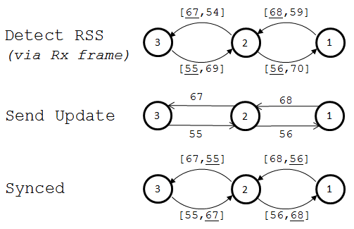
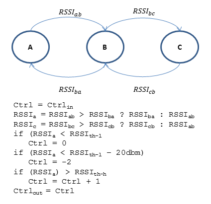
To account for this, I had each node keep track of RSS to its neighbor nodes on each received packet. Every second, nodes would transfer their most recent record of perceived RSS to its neighboring node. Each would keep a running average of the 10 most recently received RSS measurements, both based on perceived strength and the neighbor’s reported strength. The node would act on whichever running average was weaker. The below illustration depicts this process in a friendlier visual manner.
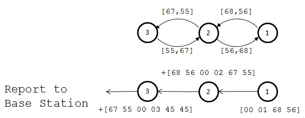
Simple, right? So what about the base station? How is the base station to monitor RSS of all nodes to provide system feedback when it only communicates with the nearest node? To provide this functionality, I implemented a message to be sent from the furthest node. The first message contains the the node’s perceived RSS to its neighbor, its address, as well as the RSS reported to it. The message is passed backwards down the chain, aggregating data concerning each node’s connections and addresses as it goes. When it finally arrives at the base station, it contains information about each node’s signal strength in the chain for that snapshot in time. This process is depicted in the image below.
I’ll point out a couple important potential criticisms. Using RSS does have some deficiency as it only represents measured signal strength, but DOES NOT represent the signal-to-noise ratio during message reception. Unfortunately, time and system constraints prevented me from facilitating the measurement of SNR, but it would be a critical piece of a deliverable system. Also, keeping a running average of the RSS is subject to some aggregation of errors, and a better option may be a running mean or some more complex filtering method.
So that’s how I handled monitoring and syncing signal strength between nodes in my application’s system. This functionality is critical as one of the primary objectives in the system is to maintain distance between nodes in order to maximize communication’s strength. In my into the primary logical functions of my system: deploying nodes as needed, maintaining distance between nodes, and healing the tether when nodes go down.
Node Deployment
When it came to the system’s responsibilities of deployment, distance management, and recovery I had to make a choice with each of how I would split that responsibility among the system parts. Should the logic for deployment be a distributed protocol among the nodes? What about healing and distance management, is that something nodes should defer to the base station? In the case of deployment, the choice of centralizing the logic to the base station was an easy one.
The process I chose to handle deployment is quite simple.
- Start-up process
- On the Node:
- After initialization, send broadcast announcing presence on one second interval
- On the Base Station:
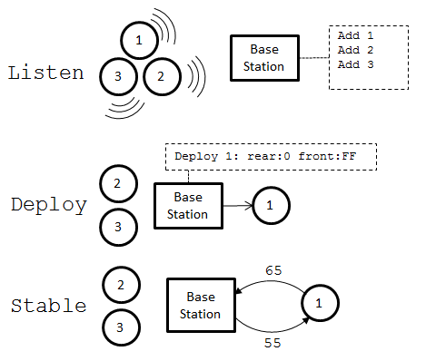
- After initialization, listen for broadcasts from new nodes
- When a broadcast is heard, add node to internal list
- After a specified start-up interval begin deploying nodes
- On the Node:
- Initial deployment:
- Base Station:
- Send message to first node assigning rear neighbor address as base station’s address
- Send deployment message (node stops broadcasting)
- Base Station:
- Continuous deployment:
- Base Station:
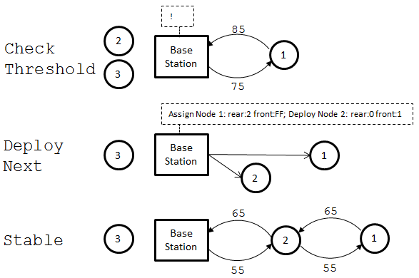
- On an interval, check measured RSS to most recently deployed(nearest) node
- If RSS drops below a set threshold (determined from testing/calculations), deploy next node:
- Send message to recently deployed node assigning rear address as next node to be deployed
- Send message to newly deployed node assigning front address as recently deployed node, and rear address as base station
- Send ‘deploy’ message to newly deployed node
- Base Station:
Of course, each assignment and deployment message is checked for an acknowledgement from the destination; if there is no acknowledgement the process bails. Further steps would be to add additional error checking on this process.
That sums up the deployment process, which is the simplest of the three system tasks. Now let’s go over the distance maintenance algorithm.
Distance Maintenance
I chose to make the distance maintenance algorithm a distributed one. The phrase ‘distributed algorithm’ tends to invoke thoughts of complexity. Implementing a distributed algorithm may require additional code to handle concurrency, error correction, message passing, etc. however in the case of my system, distributed means that I could avoid that complexity as well as increase the speed of response.
My final method was actually rather simple and relied on emergent behavior.
- Distance Maintenance Process:
- Continually move forward
- If RSS to rear is too low, slow down
- If RSS to rear is exceptionally low, stop
- If RSS to front is too high, stop
Thus the steps to implement are considerably simple. By making each nodes take these actions, the result is the tether acting as sort of a ‘spring.’ If a node moves forward, it effectively ‘pushes’ the node in front of it forwards as well. Each node will ‘pull’ the node to the front back towards it if it goes to far. If you’ve ever read up on Boids, you’ll find this similar. I wasn’t directly inspired by the work on Boids, but I suppose you could say I was indirectly inspired because I had heard of similar things in a TED talk (which I cannot remember the name of).
To compare, if I had decided to centrally control distance, it would require the base station to perform a computation on what it knows of signal strengths in the tether. Because of the work I described in part three, the base station does have this information, though it may be slightly outdated when the base station would get around to computing. The base station would also need to send at least one message down the chain to notify each node of its needed control output. This adds layers of latency and possible errors in the process, whereas by having each node process individually it doesn’t require any additional messages and causes immediate changes in control output.
Unfortunately, as I mentioned earlier, I never was able to acquire materials to make the nodes truly mobile, so I had to simulate movement by lighting LEDs and moving the nodes with my hands. I did write code for an output to servo motors. Maybe sometime in the future I will acquire a series of Arduino’s just to see this step, because it would be really cool to watch this be performed autonomously.
So that covers how I implemented a simple, distributed, emergent algorithm to allow the mobile nodes in the system of my thesis to control their distance to each other. Now let’s look at the final and most difficult piece: handling recovery when nodes area lost.
Healing the Tether when Nodes are Lost
If a node is lost, the nodes need not just to intelligently reconnect, they most likely also need to maneuver to be back in range of a healthy node. Once again there came the choice of whether to handle this distributively or centrally, and I once again chose the former.
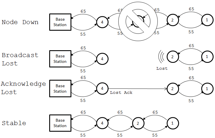
Any node in the system is expecting to hear from its neighbor to the front or rear at least once on every one second interval, so I made each node assume it had lost contact with a neighbor if it hadn’t heard anything in a small multiple of that time frame. If the neighbor was deemed lost the scenario is as follows:
- If lost neighbor to rear:
- Begin to move backwards to approach remaining tether
- Begin sending ‘lost broadcast’ message announcing it’s lost its rear neighbor
- Upon reception of acknowledgement to lost broadcast, set new neighbor as neighbor to rear
- Resume standard operation
- If lost neighbor to front:
- Send notification to base station (debug purposes)
- Continue to move forward as normal (will approach chain in front)
- Listen for ‘lost broadcast’
- Upon reception of ‘lost broadcast’ send acknowledgement, set sender as front neighbor
So, with the other steps handled the way they are, handling a lost node is actually kept rather simple. The only interruption to normal movement is the node to the front of the lost node moving backwards to recover the tether, all nodes in front of that node will move backwards to follow when RSS drops (see part five). Just as distance maintenance is handled by emergent behavior as the result of a few simple steps, so is healing the tether.
“What about the base station?” you may ask. Won’t it continue to think that the tether includes the lost node because it deployed them in a certain order? Fortunately, no. If you’ll remember from part three, the base station receives a report from the furthest node every second containing aggregated data about each connection in the chain. If at any point the order of nodes doesn’t match the base station’s record, it will update the record to match current data.
That gives a general overview of how my application handles situations where a node is lost. Once again not too complicated given the other layers are designed well.
Summary
Thus concludes the ‘blog-ification’ of the work I did on my thesis. I spared intricate details on coding and such, because that would drag on longer than I would wish for what I wanted to get across. I will give a post soon on the basics of using API mode with XBees using Python and Arduino that will include code from this project. Hopefully the general overview of how I implemented a system of mobile nodes/a base station to provide an automated wireless communications tether can be helpful to others with a similar project and/or may have just been entertaining to read.
In summary the stages of work I did on my thesis were:
- Networking - message routing and error handling
- Syncing RSS (signal strength) among nodes and base station.
- Automatically deploying new nodes from the base station
- Maintaining distance between nodes for optimal commmunications strength
- Healing the tether when a node is lost
A seemingly complicated task at first, made simple by splitting it up into parts and iteratively hacking away step-by-step. Hope you enjoyed reading!